Archived Content
Information identified as archived is provided for reference, research or recordkeeping purposes. It is not subject to the Government of Canada Web Standards and has not been altered or updated since it was archived. Please contact us to request a format other than those available.
Comprehensive Study Report
The Proposed White Rose Offshore Oil Development
- 2.1 Project Description
- 2.2 Construction and Installation
- 2.3 Development Drilling and Well Completions
- 2.4 Production Operations
- 2.5 Decommissioning and Abandonment
- 2.6 Project Schedule
- 2.7 Environmental Management System
The Proposed White Rose Offshore Oil Development
2.1 Project Description
The White Rose oilfield will be developed using subsea completions tied back to a mono-hull type FPSO unit, moored in approximately 125 m of water, with the crude oil transported to market by shuttle tankers. The following sections provide a description of the various components and activities associated with the proposed project. A more detailed project description is provided in the Comprehensive Study (Husky Oil 2000a; 2001a).
2.1.1 Production System
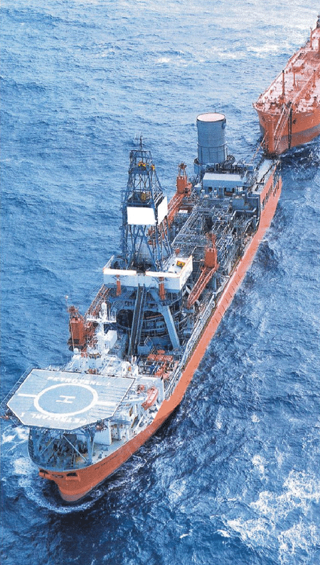
The FPSO is a floating, production, storage and offloading ship-shaped vessel (a typical North Sea steel FPSO facility is illustrated in Figure 2.1). Production facilities are mounted on raised supports above the vessel deck. Reservoir fluids pass from subsea production wells, via flowlines and risers, up into the turret and then to the production facilities. Produced oil is stored in the vessel cargo tanks and periodically offloaded onto a shuttle tanker via a loading hose.
The FPSO hull will be approximately 200 to 300 m in length, 40 to 45 m in breadth and 22 m in depth, ice-strengthened and have a lightship weight of approximately 31,000 t supporting a topside process plant, with a dry weight of approximately 7,300 t. The FPSO will be moored using a geo-stationary turret, which is anchored to the seabed. The turret mooring will be disconnectable to allow the FPSO to move to avoid iceberg threat. The vessel will rotate ('weather vane') around the turret to take up a position of least resistance to the ambient conditions with the bow heading into the prevailing wind and waves.
The FPSO will have a storage capacity of approximately 111,000 to 135,000 m³ (700,000 to 850,000 barrels) representing about 8 to 10 days of oil production. It will be capable of handling peak oil production of between 12,000 to 18,000 m³ (75,000 to 110,000 barrels) per day, peak gas production of between 6 million and 7 million m³ per day, and peak water production of between 15,000 and 30,000 m³ per day. Due to the presence of icebergs at the field location, the FPSO will have the added capability to disconnect and move off location under its own power.
The FPSO will be positioned between the glory holes and will receive production via flowlines that deliver reservoir fluids through the turret located near the bow of the vessel. Stabilized oil will be offloaded to a shuttle tanker from the stern of the FPSO via a loading hose. For conservation purposes, produced gas will be compressed and re-injected back into geological formations through the turret via dedicated flowlines.
Figure 2.1: Typical North Sea Steel FPSO Facility

While facility designs are very preliminary at this point, the proponents expect that the processing requirements will be based on a single processing train and will not require any unconventional facilities. The oil will be stabilized in a conventional separation train and de-watered in an electrostatic coalescer. The gas will be compressed for re-injection in a multi-stage compression train. The proposed configuration comprises a two or three-stage compression system driven by gas turbines.
Accommodations will be located either at the stern or the bow of the vessel to enhance segregation from process facilities. The facilities containing oil and gas will be located a safe distance from the accommodations. Typical personnel levels will range from 45 to 50 permanent crew and up to 80 to 85 with temporary crew. The accommodations requirement for the FPSO will consider the requirements for normal operation and also offshore hook-up and commissioning and maintenance operations.
The topside facilities will primarily be located on a horizontal plane raised above the vessel deck. It is envisaged that the topsides will be configured in pre-assembled units, modules or pallets. The number and size of units will be determined as design engineering is undertaken. Some of the topsides utilities include: produced and oily water treatment; seawater filter and injection systems; power generation; cooling and heating systems; fuel and inert gas systems; flare and vent system; drain systems; chemical injection; potable, service and fire water; nitrogen; diesel and jet fuel; compressed air; hydraulic power; de-icing; and safety and control systems.
Personnel safety and environmental protection will be important considerations in designing the facilities. This will apply to layout and construction and to the provision of safety systems, which will include: emergency shutdown valves; emergency flare and blowdown; hazardous waste drain; fire and gas detection; active and passive fire protection; personnel escape routes; temporary safe refuge and evacuation; energy conservation; and gaseous and liquid discharges.
Communications are a critical component in the operation of an offshore oil facility, ensuring both the safety of the facility and its competent operation. The FPSO, on-shore facilities, and all support craft will be linked by state-of-the-art communications systems for voice, data and video. Generators will be sized to meet the electrical loads of the FPSO vessel, both for normal and emergency operation. They will be able to function on produced gas or diesel. As well, there will be provision for further diesel-driven power generation for emergencies.
2.1.2 Subsea Facilities
The subsea facilities for White Rose will include all equipment necessary for the safe and efficient operation and control of the subsea wells and transportation of production and injection fluids between the wells and the FPSO. The subsea facilities include all wellhead completion equipment, trees, manifolds, flowlines, umbilicals, risers, seabed structures, control systems and all interfaces required to control and operate the facilities and associated test, installation, inspection and maintenance equipment.
Subsea wellheads will be located in glory holes to protect them from iceberg scour. Equipment within the glory hole will be designed such that the top is a minimum 2 to 3 m below the mudline, below maximum observed scour depths. Manifolds and flowlines will be designed fail-safe to minimize any harmful environmental consequences should they fail or be damaged. Flowline systems will be designed to allow the flushing/purging of production lines in the case of iceberg scour risk. Their location on the seafloor will provide ease of access for inspection, testing, repair, replacement or removal. Emergency shutdown valves will be provided to ensure the safety of personnel and minimize environmental effects in the event of accidental damage to the production facilities.
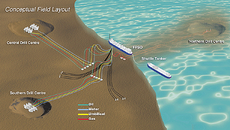
A conceptual layout of the subsea facilities is shown in Figure 2.2. The current basic conceptual field layout for the White Rose Project contains three glory holes which are to be excavated and located in proximity to the FPSO:
- 1 - to the north (approximately 7 km);
- 2 - to the south (approximately 2.5 km); and
- 3 - to the west (approximately 2.5 km).
Each glory hole is a rectangular excavation of approximately 30 m long x 20 m wide x 11 m deep, with sloping sides of 3:1 gradient.
2.1.3 Export/Transportation System
The offloading facilities will be located at the stern of the FPSO and incorporate a fiscal metering system as an integrated package. The offloading system and offloading rate will be designed with regard to the environmental conditions in the field, such that the availability of the facility is not compromised by weather limitations relating to the shuttle tanker connecting or remaining connected.
Figure 2.2: White Rose Conceptual Field Layout

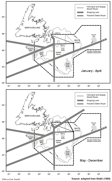
The proponents have not determined the ultimate destination of the crude. Shuttle tankers will be used for exporting White Rose crude to markets in Eastern North America, the U.S. Gulf Coast, other international destinations as well as to a transshipment facility, such as the ones currently operating at Whiffen Head, Newfoundland or Statia, Nova Scotia. Depending on the distance to market and on the volumes of crude to be exported, one to three tankers will be required. They will be double hulled, and sized appropriately for the transportation requirements. The incremental shuttle tanker traffic associated with this project (and thus, that which is assessed in this report) will occur within transportation routes over the Grand Banks area to the entrance to the International Shipping Lanes. Those shipping lanes used by international ship traffic are governed by international conventions, and mariners transporting White Rose crude will be contractually bound to follow those conventions (such as the International Convention for the Prevention of Pollution from Ships (MARPOL), and the International Convention on Oil Pollution Preparedness, Response and Cooperation (OPRC)), as applicable, and relevant Canadian federal legislation (such as the Canadian Shipping Act). The transportation routes to the major shipping lanes relevant to White Rose are depicted in Figure 2.3.
The decision as to whether or not the shuttle tankers will be Canadian flagged will be determined by the ultimate contracting strategy for the vessels. In any case, cargoes lifted from White Rose will be done using 1st Class Tonnage and reputable operators. Cargoes being shipped into Canadian destinations on a regular basis would most likely involve Canadian flagged vessels.
Figure 2.3: Transportation Routes Relevant to White Rose

2.2 Construction and Installation
Initial design engineering is forecast to start several months prior to project sanction in order to meet the target date for First Oil and enhance project viability. Any procurement decisions that must be made prior to receiving regulatory approvals would be subject to the successful outcome of the regulatory review process and project sanction. Project sanction by the proponents, which is conditional upon receiving regulatory approval and confirming commercial viability, would initiate the project and lead into construction, installation and commissioning. The target date for First Oil is approximately 36 months following project sanction. All onshore construction and fabrication activities are expected to be carried out at existing industrial sites.
2.2.1 Floating Production, Storage and Offloading Facility Construction
Historically, the hull or superstructure and topsides of FPSO vessels have been built in separate facilities in different locations, which is also expected to be the case for White Rose. Currently, there is no Canadian shipyard with a drydock capacity large enough to construct the hull. A modular approach will be followed for fabrication of the topsides. The size of individual modules depends on the lifting capacity available at the shipyard and Canada-Newfoundland benefits considerations. The turret is normally fabricated in two sections; the lower is incorporated into the hull and the upper is lifted on later. Structural sections are prefabricated and assembled, either on the hull or separately for later lift into place. The topside facilities are normally manufactured in pre-assembled units, modules or pallets. The hull and upper turret, topside facilities and other equipment are delivered to an at-shore assembly site for hook-up, mechanical completion and testing prior to proceeding to the production site.
2.2.2 Subsea Facilities
Specialized manufacturers will supply flexible line production and injection risers, suitable for use in the harsh environment at White Rose. The risers are typically supplied fully equipped and tested, and ready for installation. Subsea manifolds and flowlines will gather the production and convey it to the risers. Manifolds include headers, piping, valves, and control equipment, mounted on a base.
Many proprietary well components will comprise high quality forgings requiring heat treatment, special welding procedures and precision machining. Tree installation will require special running and testing tools. Flowlines will be either flexible or rigid steel pipe. Flexible flowlines will be prepared by the manufacturer, ready for installation. Rigid steel pipe will be manufactured by mills in lengths appropriate to transportation and handling constraints, and the limitations of the lay barge. Consideration will be given to the option of installing the flowlines in cased bundles. In that event, the flowline bundle will be fabricated on-shore at a suitable construction site. Another option, which may be examined for rigid steel pipe, is welding them into long strings on-shore and winding them onto spools on a reel lay vessel for offshore installation.
Depending on their size, manifolds may be installed either directly through the moonpool of a semi-submersible drilling unit or, if small enough, from the deck of a support vessel with sufficient lifting capacity to handle lowering them to the seafloor, where they could be picked up and placed by a drilling unit.
A dynamically positioned vessel, equipped for flexible pipe and cable installation, will be used to install the risers and flowlines. Divers may be required to make the subsea connections.
Wellheads will be installed in the glory holes through the moonpool of the drilling unit. Upon completion of the well-drilling operation, the drilling unit will also be used to install the subsea trees. Final connection of the wells to the manifolds by jumper spools may be carried out by divers.
2.2.3 Marine Support Vessels
The proponents are proposing to charter existing marine support vessels from contractors for resupply services, standby duties and ice management functions.
2.2.4 Drilling Services
One or more semi-submersible drilling units will be used throughout the life of the field for drilling, re-entering and completing wells. These units will be chartered. The unit or units will be moored at each well location supported by onboard chain and anchors. Marine support vessels, with anchor-handling capability, will be used to deploy and retrieve anchors in conjunction with rig anchor-handling equipment.
2.3 Development Drilling and Well Completions
Since the discovery in 1984 of the White Rose field, with the drilling of the N-22 well, eight additional delineation wells have been drilled and suspended or abandoned.
Of the up to approximately 18 to 25 wells required to develop the White Rose oil reservoir, up to 10 to 14 will be producing wells, six to eight will be water injection wells and two to three will be gas injection wells.
Initially, up to 10 wells will be drilled before field production begins. Plans are for wells to be drilled in clusters. Semi-submersible mobile offshore drilling units will be used to drill and complete these wells before the arrival of the FPSO. The remainder will be drilled in parallel with producing operations to meet the depletion plan objectives. The current plan is to start drilling several months after project sanction is received.
White Rose development well completions design is intended to maximize well productivity, while achieving appropriate levels of risk and well integrity. Well performance modelling based on the reservoir properties of the discovery and delineation wells has been conducted for both flowing and artificial lift (gas lift) scenarios. The flowing well model suggests that initial oil rates of between 2,800 and 4,200 m³/d are possible from horizontal development wells completed with 140-mm tubing. A well with average reservoir properties should flow at 3,600 m³/d of oil prior to water or gas breakthrough.
Water production associated with White Rose oil production is expected to increase gradually for the first 8-9 years, followed by a steady decline. The flow modelling mentioned above indicates that oil wells will require artificial lift when water cut exceeds 40 percent. Gas lift will be a readily available means of artificial lift, with gas compression facilities required for the reinjection of produced gas. Gas lift also has advantages over other means of artificial lift because it has high reliability and efficiency.
Prior to the start of production, all wells in a given glory hole will likely be batch completed after being drilled and temporarily suspended. At the end of batch drilling operations, the wells will be left with proper barriers in place and the subsea trees will be fitted with back pressure plugs and external debris covers.
2.4 Production Operations
Husky Oil will be the Operator of the White Rose oilfield on behalf of itself and its co-venturer Petro-Canada. The operation will be managed from the Husky Oil office in St. John's, where the operations management will be located. The day to day management and control of all offshore operations will be the responsibility of the Offshore Installation Manager (OIM), who will be located on the FPSO.
The on-shore organization will be structured to provide total support for all offshore operations during the development and operations phases. The on-shore organization will include personnel with all the requisite skills, knowledge, and experience for ensuring competent support to the offshore operation, even in emergency situations. It will be focused on flexibility, efficiency and cost-effectiveness. The permanent core of the on-shore organization team is expected to be 45 to 50 people. There will be additional personnel on-shore, including: helicopter air and ground staff; dockworkers and crane operators for supply vessel operations at the shorebase; and support for the supply and standby vessels.
The offshore organization will consist of skilled personnel in all disciplines required for safe, efficient, and environmentally responsible operation of all offshore facilities. The OIM will be responsible for managing the FPSO facility. Semi-submersible drilling units, each of which will be the responsibility of a dedicated onboard OIM, will carry out all drilling. The FPSO OIM will, however, have responsibility for coordinating all offshore activities. These include drilling workover, diving and ice management, in addition to the FPSO-related activities of production, storage, offloading and shipping.
The normal crew complement for the FPSO is expected to be approximately 45 to 50 people at any one time. Provision for rotation requires that this number be doubled, giving an FPSO staff strength of some 90 to 100 personnel. Each drilling vessel will require some 70 to 100 drilling and support staff during drilling and testing operations. To provide for rotation, this means a requirement of some 140 to 200 personnel per drilling unit.
Specific operations and maintenance management systems will be in place for the White Rose oilfield development. The systems will comply with all regulatory requirements, and personnel will be trained to operate in accordance with the manuals and procedures. The systems will cover the following topics: systems and equipment; reporting relationships; maintenance; production and marine operations; ice management; health and safety; emergencies; alert and contingency plans; and environmental control and monitoring.
Husky Oil already has an Ice Management Plan in place for its offshore exploration program. This plan will be reviewed, updated and/or modified, as appropriate, for application to the production phase of the White Rose oilfield development. It will be integrated with and draw upon the experience of other operators on the Grand Banks, together with the latest techniques and developing technologies, to produce the optimum plan for ice management/avoidance for the White Rose development. It will cover both sea ice and icebergs, and will be flexible in recognition of the fact that the sea ice and iceberg conditions at the South White Rose area vary considerably from year to year.
The proponents intend to investigate all possibilities of cooperation with other operators in the prospective use of shared services and facilities to support offshore operations.
Contingency plans will be prepared for dealing with major emergencies threatening personnel safety or facility integrity. These plans will comply with the requirements of Section 51 (3) of the Newfoundland Offshore Area Production and Conservation Regulations. Contingency plans and standard operating procedures to be implemented for White Rose include: emergency response; vessel specific emergency response; collision avoidance; ice management; oil spill response; ship's oil pollution emergency; and emergency communications and family support.
The proponents will cooperate with other operators and agencies in all emergency situations through resource sharing and mutual aid, and will also participate in joint training exercises with other operators.
A loss management program will be in place specific to the White Rose development which will be in keeping with Husky Oil's corporate loss control management philosophy. This philosophy is based on eliminating or reducing risks to personnel, assets, production, and environment through a continuous and systematic approach. It covers all aspects related to health and safety, environment, reliability, management of process hazards, risk assessment and loss control (additional information is provided in the Comprehensive Study, (Part One) Chapter 8).
2.5 Decommissioning and Abandonment
At the end of the production life of the White Rose oilfield development, the operator will decommission and abandon the site according to C-NOPB requirements and Newfoundland Offshore Area Production and Conservation Regulations. The floating production facility will be removed from the oilfield. Subsea infrastructure will be removed and the wells will be plugged and abandoned.
2.6 Project Schedule
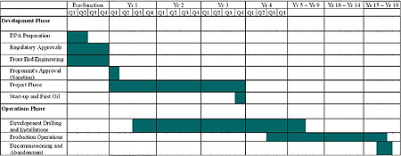
A project development schedule is provided in Figure 2.4.
2.7 Environmental Management System
Husky Oil has developed and implemented a Health, Safety and Environment Policy that guides the company in all aspects of its business. The policy is endorsed by the Chief Executive Officer and the Manager of East Coast Development and Operations. The Health, Safety and Environment Policy statement is supported by Husky Oil's East Coast Operations Health, Safety and Environmental Loss Control Management Performance Standards.
The key elements of Husky Oil's environmental management system include:
- functional/departmental responsibility for health, safety and environment;
- employee rights;
- individual responsibility for health, safety and environment;
- quality assurance;
- organizational rules;
- environmental clauses for contractors;
- environmental audits, including health, safety and environment inspections and preventative maintenance;
- environmental performance targets for atmospheric emissions, discharges, solid wastes and hazardous/dangerous materials handling;
- mitigation measures for routine activities;
- chain of command for environmental decision-making;
- environmental protection procedures;
- environmental effects monitoring (EEM) procedures and reporting;
- environmental compliance monitoring practices and reporting; and
- optimization measures for the fishing industry.
Details of the environmental management system are provided in the Comprehensive Study (Part One, Chapter 8).
Figure 2.4: Project Development Schedule

- Date Modified: